O Instituto de Arquitectura do Japão (AIJ) apresentou uma série de cenários de referência bem conhecidos para a simulação de vento.
O seguinte artigo é sobre o "Caso E - um complexo de edifícios numa área urbana real com uma densidade alta de edifícios na cidade de Niigata".
A seguir, o cenário descrito é simulado no RWIND2 e os resultados são comparados com resultados simulados e experimentais da AIJ.
O Instituto de Arquitectura do Japão (AIJ) já foi considerado um Benchmark-Szenarien für Windsimulation vorgestellt.
Der Nachfolgende Beitrag dreht sich dabei um den "Caso A - torre com a forma de 2:1:1".
Im Folgenden wird das beschriebene Szenario in RWIND2 nachgebildet und die Ergebnisse mit den simulierten und der experimentellen Resultate des AIJ verglichen.
O Instituto de Arquitectura do Japão (AIJ) apresentou uma série de cenários de referência bem conhecidos para a simulação de vento.
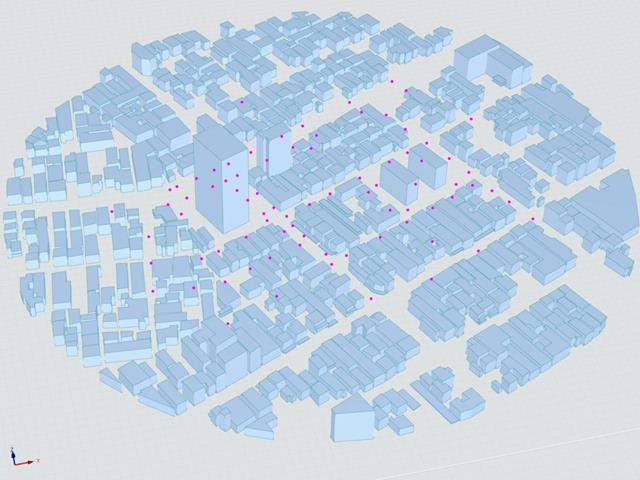
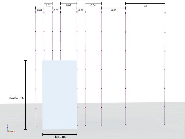
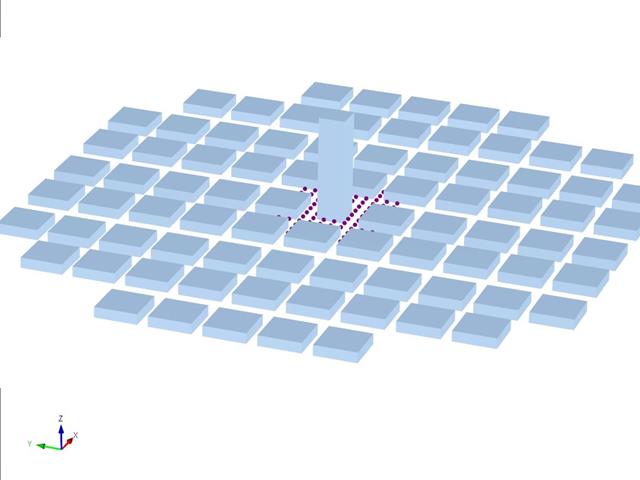
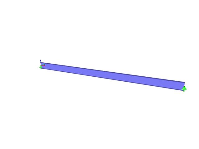
O seguinte artigo trata do "Caso D - Torre entre quarteirões".
A seguir, o cenário descrito é simulado no RWIND2 e os resultados são comparados com resultados simulados e experimentais da AIJ.
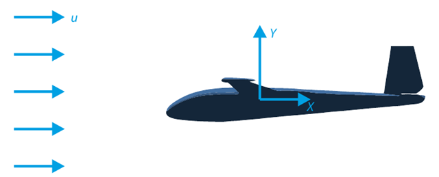
Um dos objetivos deste exemplo de verificação é analisar o fluxo de fluido em torno do planador. A tarefa consiste em determinar o coeficiente de arrasto e o coeficiente de sustentação em relação ao ângulo de ataque. Estes coeficientes também podem ser introduzidos no diagrama da curva polar de arrasto. O ângulo limite para o fluxo de fluido laminar em torno do perfil da asa também pode ser determinado a partir do campo de velocidades. O modelo CAD 3D disponível (ficheiro STL) foi utilizado no RWIND 2.
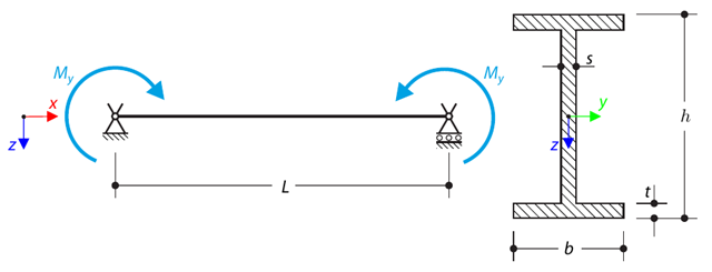
Nos apoios da forquilha está integrada uma estrutura constituída por um perfil em I. The axial rotation is restricted on both ends while warping is enabled. The structure is loaded by two transverse forces in the middle. The verification example is based on the example introduced by Gensichen and Lumpe.
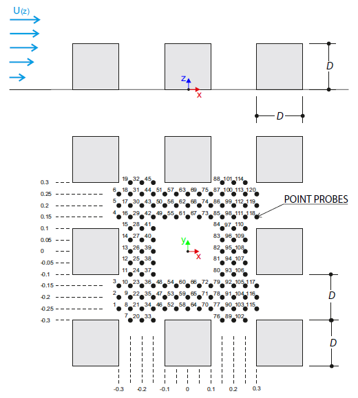
O exemplo de verificação descreve cargas de vento em várias direções do vento num modelo de um grupo de edifícios. The model consists of eight cubes. The velocity fields obtained by the RWIND simulation are compared with the measured values from the experiment. The experimental data are measured using a thermistor anemometer in the wind tunnel.
This verification example compares wind load calculations on a duopitch roof building using the ASCE 7-16 standard and using CFD simulation in RWIND Simulation. O edifício é definido conforme o esboço e o perfil da velocidade do fluxo contido na norma ASCE 7-16.
This verification example compares wind load calculations on a flat roof building using the ASCE 7-16 standard and using CFD simulation in RWIND Simulation. O edifício é definido conforme o esboço e o perfil da velocidade do fluxo contido na norma ASCE 7-16.
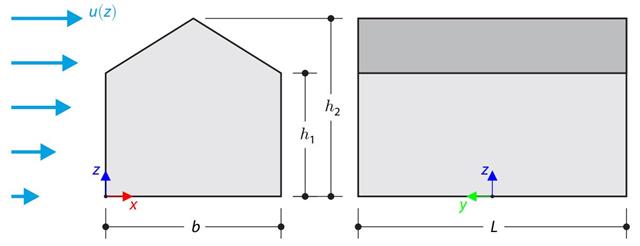
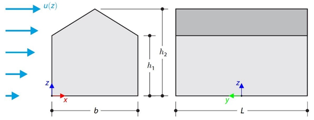
No exemplo de verificação, o cálculo de cargas de vento num edifício com cobertura de duas águas utilizando a norma EN 1991-1-4 é comparado com uma simulação CFD no RWIND Simulation. The building is defined according to the sketch, and the inflow velocity profile is taken according to the standard EN 1991-1-4.
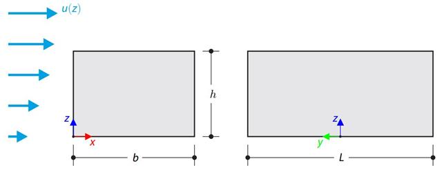
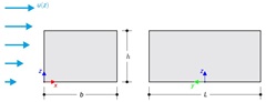
No exemplo de verificação, o cálculo da carga de vento num edifício com cobertura plana utilizando a norma EN 1991-1-4 é comparado com uma simulação CFD no RWIND Simulation. The building is defined according to the sketch, and the inflow velocity profile is taken according to the standard EN 1991-1-4.
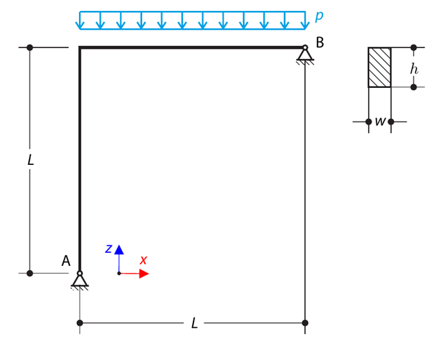
A simply supported beam is loaded by pure bending. Devido à encurvadura por flexão, tente determinar a carga de encurvadura crítica e o fator de carga correspondente.
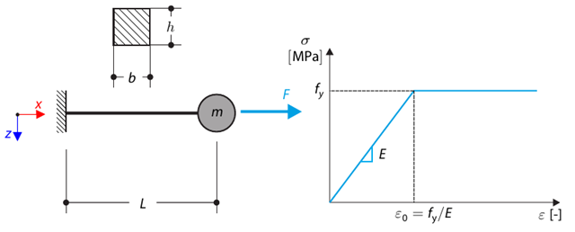
Este exemplo de verificação é baseado no exemplo de verificação 0122. A single-mass system without damping is subjected to an axial loading force. An ideal elastic-plastic material with characteristics is assumed. Determine the time course of the end-point deflection, velocity, and acceleration.
Uma estrutura plana simétrica é constituída por oito treliças idênticas encastradas em apoios articulados. The structure is loaded by a concentrated force and alternatively by imposed nodal deformation over the critical limit point when the snap-through occurs. Imposed nodal deformation is used in RFEM 5 and RSTAB 8 to obtain the full equilibrium path of the snap-through. The self-weight is neglected in this example. Determine the relationship between the actual loading force and the deflection, considering large deformation analysis. Evaluate the load factor at the given deflections.
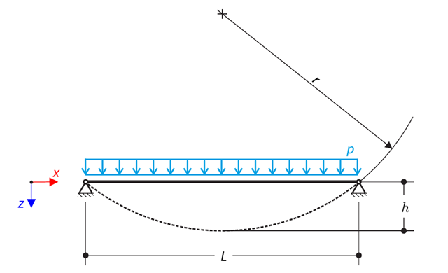
A cable is loaded by means of a uniform load. Isto resulta numa forma deformada de um segmento circular. Determine the equilibrium force of the cable to obtain the given sag of the cable. The add-on module RF-FORM-FINDING is used for this purpose. Elastic deformations are neglected both in RF-FORM-FINDING and in the analytical solution; self-weight is also neglected in this example.
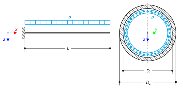
A pipe with a tubular cross-section is loaded by internal pressure. This internal pressure causes axial deformation of the pipe (the Bourdon effect). Determine a deformação axial do ponto de extremidade do tubo.
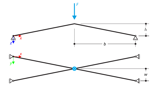
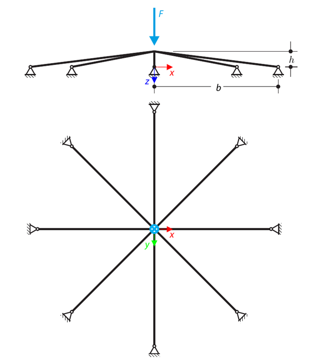
Uma estrutura é constituída por quatro treliças encastradas em apoios articulados. The structure is loaded by a concentrated force and alternatively by imposed nodal deformation over the critical limit point, when snap-through occurs. Imposed nodal deformation is used in RFEM 5 and RSTAB 8 to obtain the full equilibrium path of the snap-through. The self-weight is neglected in this example. Determine the relationship between the actual loading force and the deflection, considering large deformation analysis. Evaluate the load factor at given deflections.
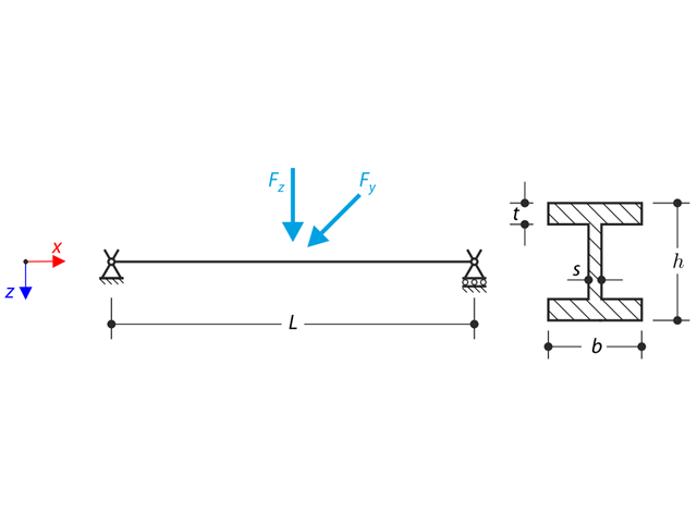
Considere o vão da barra ASTM A992 W 18×50 apresentado na Figura 01 e as cargas permanentes e variáveis uniformes. The member is limited to a maximum nominal depth of 18 inches. The live load deflection is limited to L/360. The beam is simply supported and continuously braced. Verify the available flexural strength of the selected beam, based on LRFD and ASD.
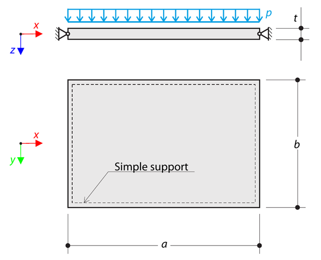
A thin rectangular orthotropic plate is simply supported and loaded by uniformly distributed pressure. The directions of axes x and y coincide with the principal directions. Determine a flecha máxima do painel, sem considerar o peso próprio.
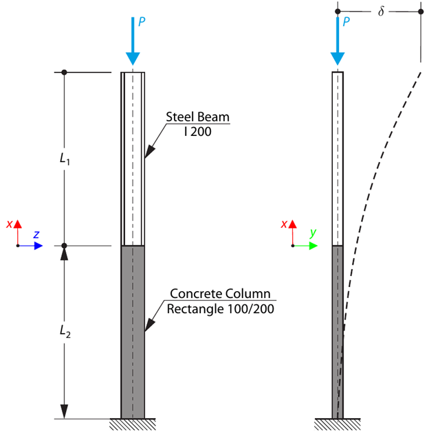
A column is composed of a concrete section (rectangle 100/200) and a steel section (profile I 200). Está sujeito a uma força de compressão. Determine the critical load and corresponding load factor. The theoretical solution is based on the buckling of a simple beam. In this case, two regions have to be taken into account due to different moments of inertia and material properties.
Uma viga curvada é constituída por duas vigas de secção retangular. The horizontal beam is loaded by distributed loading. While neglecting self-weight, determine the maximum stress on the top surface of the horizontal beam.
Um recipiente cónico de parede fina está cheio de água. Thus, it is loaded by hydrostatic pressure. While neglecting self-weight, determine the stresses in the surface line and circumferential direction. The analytical solution is based on the theory of thin-walled vessels. This theory was introduced in Verification Example 0084.
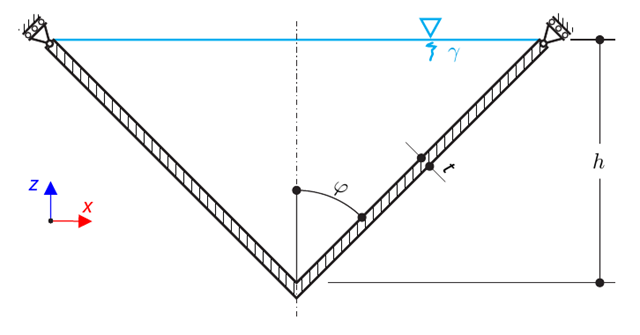
A closely coiled helical spring is loaded by a compression force. The spring has middle diameter D, wire diameter d, and it consists of i turns. O comprimento total da mola é L. Determine the total deflection of the spring for the member model and one‑turn deflection for the solid model.
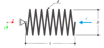
Um oscilador simples é composto por massa m (a ser considerada apenas na direção x-) e pela mola linear com a rigidez k. The mass is embedded on a surface with Coulomb friction and is loaded by constant-in-time axial and transverse forces.
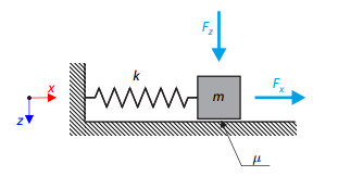
A bimetallic strip is composed of invar and copper. The left end of the bimetallic strip is fixed, and the right end is free, loaded by temperature difference. Determine a flexão da tira bimetálica (na extremidade livre), sem considerar o peso próprio.
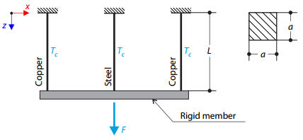
A truss structure consists of three rods (one steel and two copper) joined by a rigid member. The structure is loaded by a concentrated force and a temperature difference. Determine a flecha total da estrutura, sem considerar o peso próprio.
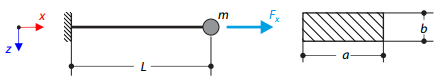
A cantilever of rectangular cross‑section has a mass at the end. Além disso, é carregada por uma força axial. Calculate the natural frequency of the structure. Neglect the self‑weight of the cantilever and consider the influence of the axial force for the stiffness modification.
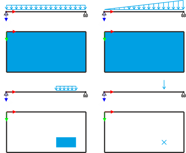
A placa retangular simplesmente apoiada é sujeita a diferentes tipos de carga. Assuming only the small deformation theory and neglecting self-weight, determine the deflection at its centroid for each load type.
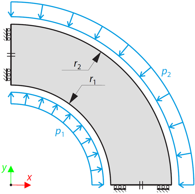
Este exemplo é uma modificação do Exemplo de verificação 0061; a única diferença é que o material do recipiente é incompressível. An open‑ended, thick‑walled vessel is loaded by both inner and outer pressure. While neglecting self‑weight, the radial deflection of the inner and the outer radius is determined.
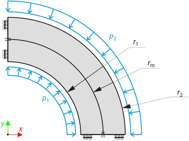
A two-layered, open-ended, thick-walled vessel is loaded by inner and outer pressure; therefore, there is no axial stress. É determinada a flecha radial do raio interior e exterior, bem como a compressão (tensão radial), não sendo considerado o peso próprio.
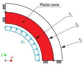
A thick-walled vessel is loaded by an inner pressure such that the vessel reaches an elastic-plastic state. São determinadas e comparadas as soluções analíticas e numéricas para a posição radial da zona de fronteira plástica (de acordo com a hipótese de Tresca), não sendo considerado o peso próprio.